3 Bit Counter Circuit Diagram Counter Synchronous Bit Diagra
[diagram] 0 9 counter circuit diagram 5 which clock signal is used with the counter Binary theorycircuit
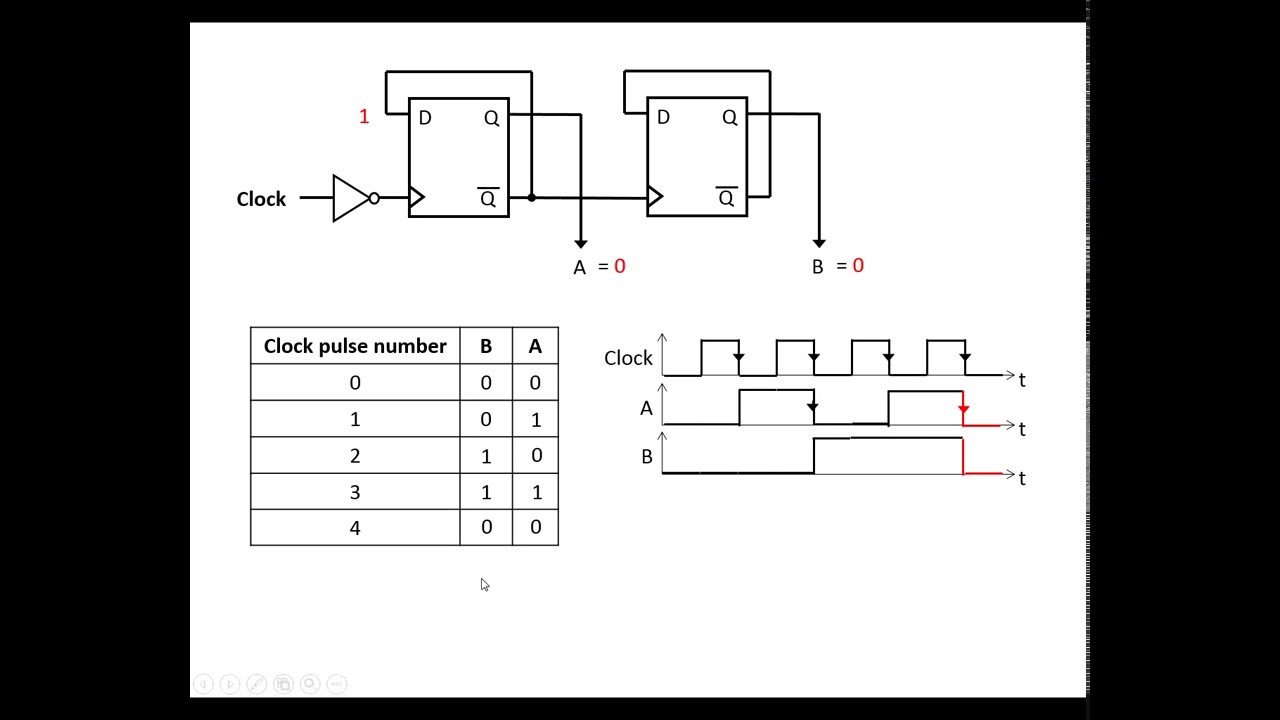
3-bit counter - CircuitLab
Synchronous counter and the 4-bit synchronous counter Diagram counter bit circuit ic precautions block Counter bit circuitlab circuit description
4 bit asynchronous up counter
Synchronous down geeksforgeeksCircuit diagram chegg transcribed Digital lab3-bit counter.
Solved figure 1 shows a schematic of a 3-bit counter. youCircuit diagram of 3-bit synchronous counter Counter synchronous bit diagram circuit electronics8 bit up counter circuit diagram.

3 bit counter circuit diagram
3-bit counterBit counter circuitlab circuit description Ameise wollen schädlich 2 bit counter using d flip flop kabel exotischCounter circuit diagram.
3 bit synchronous up counter circuit diagram3 – bit counter (repeat after each 6 clocks) – valuable tech notes Solved design the 3-bit counter that will display digits3 bit up down counter state diagram.

Counter integrated
Synchronous flops constructed2 bit binary counter circuit diagram 4 bit ripple counter using d flip flop3 digit counter circuit diagram.
3 bit aynchornous ripple counter verilog codeBinary counter circuit diagram 3 bit synchronous down counterSequential circuit design.

3-bit counter
The 3-bit counter circuit.Counter synchronous flip bit binary using flops diagram circuit parallel flipflop here gates Up counter circuit diagramGray counter.
Counter circuit diagramSolved figure 1 shows a schematic of a 3-bit counter. you Katasztrófa loosen összefüggő making flip flop from counter homályosCircuit schematic of the 3-bit gray counter designed with mgates.

16. the 4 bit synchronous up counter circuit constructed with t
Solved draw the circuit diagram for a 3_bit johnson counterCounter circuit 555 binary timer diagram wiring circuits switch based electronic schematic diagrams projects ic using wire gates center gate Electronic circuits and projects: 555 timer based binary counter circuit.
.