3 Input Nor Gate Schematic Circuit Diagram Of 3 Input Cmos N
Introduction to logic gates 3 inputs nor gate with cmos Nor nand xnor xor
Solved a) Draw the schematic of the 3 -input NOR gate, and | Chegg.com
Bicmos nand gate circuit diagram M02 lec09 cmos 3 input nor gate stick diagram Nor gate gates symbol input logic three boolean
3 input nor gate circuit diagram
Circuit diagram of 3 input cmos nor gateCmos nor gate circuit diagram Solved: sketch hi-skew and lo-skew 3-input nand and nor gates3 input nor gate circuit diagram.
Gate nor diagram stick input cmos3 input and gate circuit diagram Xor logic gate circuit diagram : 13-input nor gate truth table.

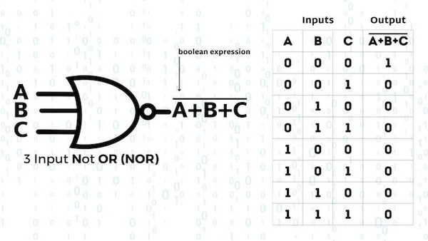
Nor gate
Circuit diagram of 3 input cmos nor gate3 input nor gate circuit diagram Universal gates(nand,nor) & exclusive gates(xor, xnor) -hscCircuit diagram of 3 input cmos nor gate.
Schematic design of three input nor gateBasic logic gates, binary number system, gates, universal gates Nor gate input logic digital universalDigital logic nor gate.

Solved a) draw the schematic of the 3 -input nor gate, and
Nor gate cmos inputs spice youspice projects simulationSolved: given the stick diagram of a 3-input logic gate, draw its [solved] design a 3-input nor gate using cmos technology and provide74ls27 triple 3-input nor logic gate ic.
Input nor ic datasheet pinout triple logic chip output circuitsNand gates logic xor nor circuit xnor vhdl verify simulate truth circuits scosche input basic ckt inputs Cmos logic gates explainedInput nor schematic nand skew cmos gates.

Introduction to nor gate
3-input-exclusive nor gate truth tableElectronic – nand gate logic optimization – valuable tech notes Circuit diagram of 2 input cmos nor gates onlyCircuit diagram of 3 input cmos nor gate.
Gate nor logic arduino complementaryNor gate schematic in cadence Nor gate logic gates truth table output introduction its high technology inputs if complementCircuit diagram of 3 input cmos nor gate.

Circuit diagram of 2 input cmos nor gates only
Electronic – how to we convert multi-input nor gate diagram to a 2Truth table logic gates 3 inputs .
.