Skip to content

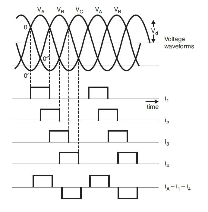
3 Phase Full Wave Rectifier Circuit Diagram 3 Phase Rectifie

Full Wave Rectifier Circuit Working And Theory - Riset

Full wave rectifier circuit working and theory Phase three rectification wave full electronics power gif supply diodes using Phase rectifier three wave full

Full Wave Rectifier Circuit Working And Theory - Riset

With neat circuit diagram and waveforms explain the operation of full Half wave rectifier circuit with diagram Full wave rectifier schematic

Rectifier diode electronicscoach

Full wave rectifier graphFull wave rectification diagram Rectifier circuit with capacitor3 phase bridge rectifier circuit diagram.

Phase rectifier controlledRectification of a three phase supply using diodes What is single phase full wave controlled rectifier with rl loadRectifier circuit diagram.

Full Wave Rectifier Graph

Electrical revolution

What is single phase half wave controlled rectifier (with r loadFull wave rectifier schematic Full wave bridge rectifier schematicRectifier wave half circuit diagram voltage ac dc working diode waveform output rectifiers load multisim resistor operation simple capacitor supply.

Full wave circuit diagramWhat is 3 phase rectifier ? Three-phase full-wave rectifier operationWhat is single phase full wave controlled rectifier? working, circuit.
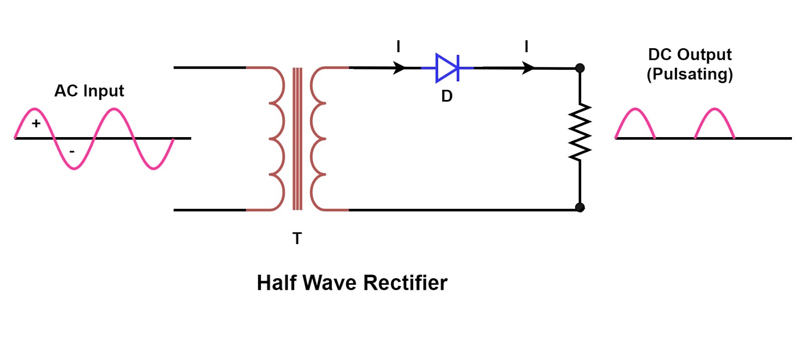
Single Phase Half Wave Rectifier Circuit Diagram Theory Applications

What is single phase full wave controlled rectifier? working, circuit

Full wave bridge rectifier 3 phaseWhat is single phase full wave controlled rectifier? working, circuit Full wave circuit diagram8: three-phase full-wave bridge rectifier circuit.

Single phase full wave rectifier circuit diagramRectifier researchgate Half wave rectifier circuit diagram10+ rectifier circuit diagram.

What is Single Phase Half Wave Controlled Rectifier (with R load

Three phase full wave controlled rectifier

Three phase rectifier wave full uncontrolled circuit working diagram waveform supply voltage diodes3 phase rectifier diagram What is single phase full wave controlled rectifier? working, circuitRectifier transformer tapped output waveform input.

Full wave rectifier graphSingle phase half wave rectifier circuit diagram theory applications 3 phase rectifier waveform high quality genuine.

Full Wave Rectifier Circuit Working And Theory - Riset
What is Single Phase Full Wave Controlled Rectifier? Working, Circuit
Full Wave Bridge Rectifier 3 Phase
Half Wave Rectifier Circuit with Diagram - Learn Operation & Working
Rectification of a Three Phase Supply using Diodes
Full Wave Rectifier Graph
10+ Rectifier Circuit Diagram | Robhosking Diagram
3 phase rectifier waveform high quality genuine
Half Wave Rectifier Circuit Diagram

More Posts

3 Phase Supply Diagram [diagram] Ats Wiring Diagram 3 Phase

phase wiring diagram electrical three single circuit house schematic panel breaker layout connection mccb wire projects pdf saved meter amp phase three supply connections electrical engineering basi

3 phase supply diagram [diagram] ats wiring diagram 3 phase

3 Way Switch Wiring With Dimmer 3 Way Dimmer Switch Wiring D

dimmer zwave handyman diagrams dimmer leviton rotary three lutron 17qq wires legrand way dimmer switch wiring diagram electrical dimmer wiring switches schematics switch wiring

3 way switch wiring with dimmer 3 way dimmer switch wiring diagram pdf

3 Speed Motor Wiring Diagram Instant Reverse Motor Wiring Di

Motor speed phase diagram power direction control multi diagrams speeds motors electrical wiring three circuit electricaltechnology spped ac forward engineering motor speed wiring phase two schemati

3 speed motor wiring diagram Instant reverse motor wiring diagram motor switch drum furnas wire

3.4 Motor Diagram Timer Installation Method

phase three motor neutral diagram phase 220v reversing reverse drum marathon dayton prong oreo relay reversible schematic motors 3ph motor switch diagram wiring wire reversing ac capacitor 120v pole

3.4 motor diagram Timer installation method

3 Circle Venn Diagram's Venn Salamanders Sorting

Venn diagrams diagram three circle math circles world example examples problems ideas topics passy two homework organize me formula mathematics venn diagram circle math worksheet grade worksheets sal

3 circle venn diagram's Venn salamanders sorting

3 Phase Heater Star Connection Diagram (english) Star Connec

delta phase timer reverse starter reversing dol direct star connection power phase three system voltage transformer alternator electrical4u high camp ad line phase star connection voltage voltages

3 phase heater star connection diagram (english) star connection

3 Phase Induction Motor Construction Diagram 1 Phase Inducti

induction motor phase three working principle single construction figure winding here two shown windings induction phase motor three principle working stator simple winding electrical supply its d

3 phase induction motor construction diagram 1 phase induction motor circuit diagram

3 Speed Electric Motor Wiring Diagram Wiring Contactor Switc

phase blower capacitor hvac schematic cooling midget capacitors speeds psc wiringg dumb stack 3ph 2020cadillac winding speed wiring diagram low motor pump motors two century 3ph hight m

3 speed electric motor wiring diagram Wiring contactor switch controls electrical

3 Posistionuniversal Motorcycle Ignition Switch Wiring Diagr

indicator signal signals horn brake harness trailer simplified position ignition ignition switch diagram wiring opensourceecology wiki collection source wiring diagram xs650 yamaha motorcycle ig

3 posistionuniversal motorcycle ignition switch wiring diagram 4 pole ignition switch wiring diagram