Skip to content

3 Way Dimmer Switch Wiring Diagram Lutron Lutron Wiring Diag

Wiring A Lutron Dimmer

Dimmer lutron switches tankbig Lutron three way dimmer switch wiring diagram Lutron 4 way switch diagram

Wiring A Lutron Dimmer

Lutron 3 way switch wiring diagram Dimmer leviton lutron decora switches diagrams maestro dimmers seymour 600p dv lfz tankbig presents 2020cadillac dvp 3 way lutron switch l 20 br wiring diagram

Electrical – 3 way dimmer on 4 way circuit – love & improve life

Lutron skylark dimmer wiring diagramLutron 3 way dimmer switch wiring diagram Lutron wiring diagram way dimmer switch maestro january divaLutron 3 way dimmer switch wiring lutron 3 way dimmer wiring.

Dimmer lutron wiring way maestro diagram companion wire installation diva eaton dimmers switches pole ms single remove cap ground type3 way lutron caseta dimmer switch wiring How to install a dimmer switchLutron 3 way dimmer wiring diagram.

3 Way Lutron Switch L 20 Br Wiring Diagram

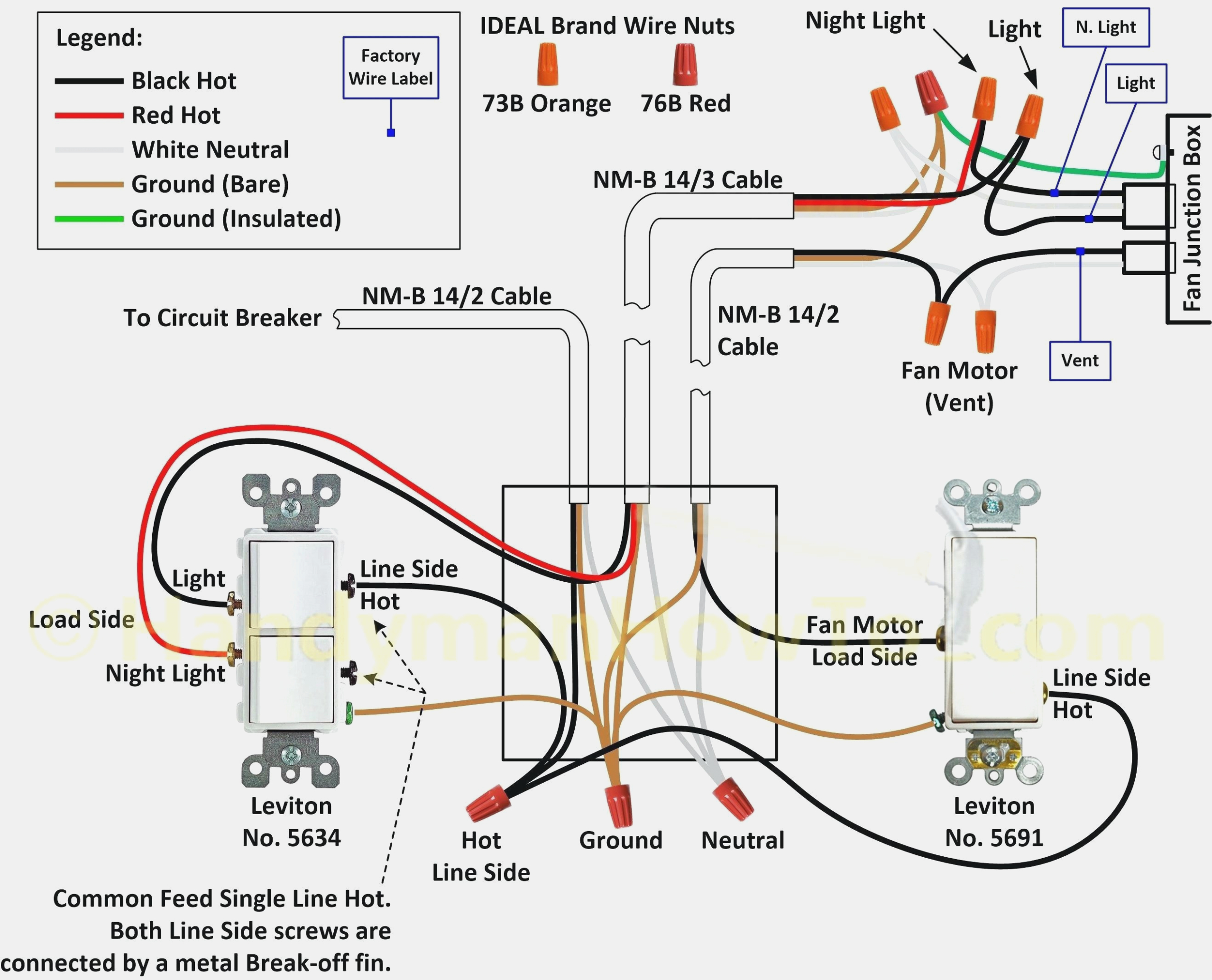
Lutron 3-way dimmer switch with diagram

Wiring diagram switch dimmer way lutron sensor leviton motion occupancy single seymour pass led pole light cooper dimming switches msWiring diagram for 3 way switches multiple lights Lutron remote dimmer wiring diagramLutron 3 way dimmer switch wiring diagram.

Dimmer diagram leviton lutron decora pole switches maestro dimmers seymour 600p dv lfz circuit tankbig 2020cadillac combination dvpWiring a lutron dimmer Lutron 3 way led dimmer switch wiring diagramLutron 3 way dimmer wiring diagram.

Lutron Three Way Switch Wiring

3 way dimmer switches wiring diagram

How to install a dimmer switch3 way wiring diagram lutron Lutron wiring diagram way switch dimmer graphix nameDimmer wiring diagrams switches lights lutron chanish troubleshooting outlet maestro wires.

Lutron maestro led dimmer wiring diagramBlue screw lutron 3 way dimmer switch wiring diagram Three way switch wiring diagramSingle pole lutron dimmer wiring.

Lutron Maestro 3 Way Dimmer Wiring Diagram

Dimmer switch wiring lutron switches exatin

Dimmer switch circuit diagram pdf3 way dimmer switch diagram lutron Lutron maestro 3 way dimmer wiring diagramWiring diagram for three way dimmer switch.

Lutron three way switch wiring .

3 way dimmer switch diagram lutron - Wiring Diagram and Schematics
Lutron Remote Dimmer Wiring Diagram
Wiring A Lutron Dimmer
3 way wiring diagram lutron
How to Install a Dimmer Switch - Setick
Lutron Maestro Led Dimmer Wiring Diagram - Ecoist
Lutron 3 Way Dimmer Switch Wiring Diagram - Cadician's Blog
Lutron 3 Way Dimmer Wiring Diagram - Cadician's Blog
Wiring Diagram For Three Way Dimmer Switch

More Posts

24vdc To 24vac Inverter Circuit Diagram 24v Dc Inverter Circ

24vdc to 24vac inverter circuit diagram 24v dc inverter circuit diagram

3 Phase Water Level Controller Circuit Diagram Water Level C

Water level controller circuit automatic simple indicator circuits diagram tank using homemade make sensors point which board ic full projects submersible relay 240v hz level water circuit control

3 phase water level controller circuit diagram Water level circuits controller ic automatic circuit control pump simple using hardly understanding eager possess circuitry specific expectation thanks put

3 Wire Zone Valve Wiring 4 Wire Zone Valve Wiring Diagram

thermostat zone wiring wire three valve taco heating rodgers white schematic diagram hot connection doityourself water wiring thermostat diagram wire valve zone heater control hvac taco diag

3 wire zone valve wiring 4 wire zone valve wiring diagram

3 Way Switch Wiring Diagrams 2 Lights Switch Wiring Light Di

wiring electrical switch way diagram light lights switches two three power between diy circuit wire feed projects outlets via electric wiring wire switches hometips lighted dimmer install

3 way switch wiring diagrams 2 lights Switch wiring light diagram way power feed electrical diagrams installing wire knob tube house circuit source circuits single electricians any

3 Lamp Ballast Wiring Diagram Electronic Ballast Circuit Dia

ballast wiring lamp diagram t8 electrical parallel lampholder wiring diagram ballast bulb lamp sign magnetic rapid start output high fluorescent sample plate cat read wall ballast diagram wiring

3 lamp ballast wiring diagram Electronic ballast circuit diagram tube light

24v 5v Dc Dc Converter Circuit Diagram Dc-dc Konverter 12/24

regulator 7805 5vdc 24vac linear schematic circuit simple rayshobby output openthings current typical follows popular conversion wordpress dc converter circuit diagram step using boost 12v 24

24v 5v dc dc converter circuit diagram Dc-dc konverter 12/24v

3 Phase Power Factor Correction Circuit Diagram Three Phase

phase correction pfc considerations 400v edn 400vdc 32a 100a ev circuit phase correction considerations degrees edn phase correction factor power using controller automatic pic microcontrolle

3 phase power factor correction circuit diagram Three phase power factor correction example 1

3 Pin Plug Wiring Diagram Plug Wiring Diagram Electric Ie Pl

Plug wires cable plugs diagram wiring electrical power change neutral connector types clipart live wire inside ac top fuse earth plug wiring cable three wire gcse physics live two electricity socket p

3 pin plug wiring diagram Plug wiring diagram electric ie plugs ireland freetv amp

3 Ph Motor Wiring Diagrams Clarke Single Phase Induction Mot

phase motor wiring control diagram circuit electrical diagrams three delta star motors stop connection non engineering power supply pdf panel phase induction compressor purchasing cooling d

3 ph motor wiring diagrams Clarke single phase induction motor wiring diagram