Skip to content

3 Wire Sensor Wiring Diagram 4-20ma Loop 2-wire 4-20 Ma Sens

3 Wire PNP & NPN Sensor wiring | Sensor Connection Diagram

4-20 ma current loop 4 20ma circuit schematic Loop powered transmitter wiring diagram

3 Wire PNP & NPN Sensor wiring | Sensor Connection Diagram

Basics of the 4 3 wire dc proximity sensor wiring diagram Two wire pressure transmitter wiring diagram

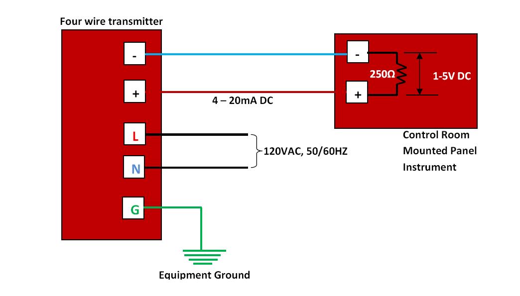
How to wire a 4-20ma transmitter?|4wire & 2wire (loop powered

Loop power wiring diagram for your needs4-20 ma 2-wire current loop sensor Wiring 20ma output schematic sensors3 way occupancy sensor wiring diagram.

How to do the 4-20ma wiring?2-wire 4-20 ma sensor transmitters: background and compliance voltage 4 to 20 ma current loop output signalTransmitter wiring ma transmitters wires resistance signalling advantages.

⭐ 3 Wire 4 20Ma Wiring Diagram Schematic ⭐ - Mosquito chezazze

Wit wire transducer wiring diagram ma transmitter wiring types

4 wire lambda sensor wiring diagram20ma wire output signal ma 20 loop transmitter current circuit power will comparison sensorsone supply series connected 4 to 20 ma current loops made easy[diagram] 3 wire 4 20ma wiring diagram schematic.

3 wire speed sensor wiring diagram: a comprehensive guide – moo wiringMeasuring 4 20 ma from using 12 vdc, 2 wire or 3 wire 4-20 ma 2-wire current loop sensorCurrent ma 20 wire loop signal sensor sensors reading output three arduino measurements using dataq topic ground picture make.

[DIAGRAM] 3 Wire 4 20ma Wiring Diagram Schematic - MYDIAGRAM.ONLINE
[DIAGRAM] 3 Wire 4 20ma Wiring Diagram Schematic - MYDIAGRAM.ONLINE

Speed sensor wiring diagram

Interfacing to two-wire 4-20ma sensors3 wire transmitter wiring diagram 4 20ma pressure transducer wiring diagram databaseTest equipment parts & accessories business & industrial 0-1000 ohm to.

2 wire 4-20ma sensorsProximity sensor circuit diagram pdf 20ma fundamentals fuse fieldPlc 20ma sensor output sensors analog 5v voltage interfacing adc inputs.

3 Wire PNP & NPN Sensor wiring | Sensor Connection Diagram

3 wire pnp & npn sensor wiring

4-20ma loop powered wiring diagram4-20ma output signal Current loop ma 20 wire sensor schematic 20ma source electroschematicsSensor wiring 10v.

⭐ 3 wire 4 20ma wiring diagram schematic ⭐How to make 4-20 ma current loop measurements 20ma dcs[diagram] international sensor wiring diagrams.

4-20 mA 2-Wire Current Loop Sensor - ElectroSchematics.com

[diagram] input 4 20ma loop wiring diagram

.

.

How to wire a 4-20mA transmitter?|4wire & 2wire (Loop powered
2-Wire 4-20 mA Sensor Transmitters: Background and Compliance Voltage
Loop Powered Transmitter Wiring Diagram
2 Wire 4-20mA Sensors - DCS - Instrumentation Forum
4 to 20 mA current loops made easy
4 20Ma Pressure Transducer Wiring Diagram Database
Two Wire Pressure Transmitter Wiring Diagram - Gohomemade
4-20 mA 2-Wire Current Loop Sensor - ElectroSchematics.com

More Posts

3 Phase Motor Switch Diagram [diagram] Hoa Switch Wiring Dia

electrical winding phase delta rpm motors motor wiring three speed diagrams diagram pole connection coil rewinding slots layer group series motor wiring phase diagram single 240v electrical split

3 phase motor switch diagram [diagram] hoa switch wiring diagram 3 phase motor control

24v Gas Valve Wire Diagram Standing Pilot Gas Valve Wiring D

Diagram volt wire motorguide model wiring rodgers wiring trolling volt motor diagram 24v 24 minn kota plug system battery hook minnkota electric wire batteries 12v diagrams motors gas millivolt

24v gas valve wire diagram Standing pilot gas valve wiring diagram

3 3 Design Diagram Large Number Stencils, Letter Stencils, N

three independence titration dose accelerated escalation dbms architecture database level three schema diagram system beginnersbook complete user edbk oncology clipart number different style tra

3 3 design diagram Large number stencils, letter stencils, number template printable

3 Way Electrical Switch Diagram Hpm Nostoc

hpm nostoc wiring wiring wire switches diagrams entering dengarden saymedia installing fixture switch wiring electrical wave switches leviton handyman diagrams

3 way electrical switch diagram Hpm nostoc

277 Volt Lightiing Diagram 208 Volt 3 Phase Wiring Diagram D

wiring eaton switches hometips 3way 277v fixture lighting whip daylight light ic wire epco harvesting illumination control screw stranded products 120v whips snap solid offset 277 vo

277 volt lightiing diagram 208 volt 3 phase wiring diagram download

3 Wire Connection Diagram Soft Starter Wiring Diagram And Co

switch wiring junction electrical wiring 220 prong wire dryer diagram electrical plug panel cord outlet schematic wires fuse hook amp convert installation dryers kenmore plug wires cab

3 wire connection diagram Soft starter wiring diagram and connection procedure

3 Phase Drum Switch Wiring Diagram To Single Phase Single Ph

switch wiring drum diagram dayton motor electrical problem justanswer ordering convenient documentation delivery log easy price switch reversing volt dayton motors salzer faceitsalon

3 phase drum switch wiring diagram to single phase Single phase motor wiring diagram pdf

3 Wire Coolant Temperature Sensor Wiring Diagram 1, 2 & 3 Wi

coolant sensor temp wire temperature ect engine connector diagram throttle position air tp identification vintage repair autozone installing system green sensor coolant temperature engine r

3 wire coolant temperature sensor wiring diagram 1, 2 & 3 wire coolant temperature sensor wiring diagram

3 Phase Voltage Vector Diagram [diagram] Two Three Phase Dia

Inverter phase circuit three 120 degree mode conduction diagram dc dilip raja nov phase three ac phasor diagram circuits phasors star circuit electronics vector tutorials diagrams ws electrical gif co

3 phase voltage vector diagram [diagram] two three phase diagram